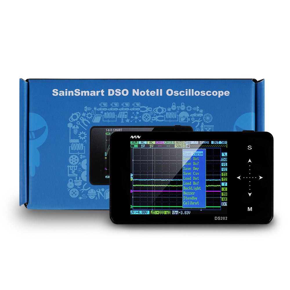

AC (This and the adjacent/lower cell control the analog CH-B input, when toggled indicates DC however, pressing down toggles to HIDE) The color associated with CH-B is yellow.AC (This and the adjacent/lower cell control the analog CH-A input, when toggled indicates DC however, pressing down toggles to HIDE) The color associated with CH-A is cyan.RUN (This appears to be a status indicator when toggling between displaying an active/changing waveform and displaying a frozen/held waveform for the purpose of measurements.).The last three menu items on the top menu correspond to the last menu item graphic on the second top menu since they go together. The same is true for digital CH-C which I am currently not displaying ("-"), for example. The same is true for "AC" + "1V" for CH-B.

In other words, "1V" in my case in the second menu row refers to the setting for "AC" which corresponds to the setup for analog CH-A. For the top two menus, what is seen in adjacent cells are connected to each other. Here, I just indicate what I'm seeing currently on my screen based upon the prior selections I made, noting that yours may show differently. The following is a list of menus seen on the LCD screen during operation after the initial splashscreen.
SAINSMART OSCILLOSCOPE KIT INSTRUCTIONS GENERATOR
WAVE OUT: Signal generator output, mcx-style connector.NAV-B: Also known as "" or Navigator B (this momentary-press switch can be pushed left or right and the middle can be pressed down).NAV-A: Also known as "-.v.+" or Navigator A (this momentary-press switch can be pushed left or right and the momentary-press middle can be pressed down as a toggle).K4: Also known as TRIANGLE or Save Wave (this is a momentary-press toggle button).K3: Also known as RECORD or Preset (this is a momentary-press toggle button, toggling this often brings up a popup display which is sometimes signal details).K2: Also known as STOP or Calibrate (this is a momentary-press toggle button).K1: Also known as PLAY or Run/Hold (this is a momentary-press toggle button).Note that ElecHouse's button listing on their p5 incorrectly labels CH-A and CH-B locations. There appear to be short-press and long-press versions of the K1-K4 controls which perform different functions. The following controls are broken down by side of the oscilloscope, as held vertically to face the LCD screen. Max input voltage of logic probe: +/- 15V peak valueįrom 's website (PDF, 13 pages)įrom 's website (PDF, 29 pages) Interface and Controls.Max transient-withstanding voltage: +/- 400V peak value.Humidity requirements: Operating (10-60% RH), Non-operating (5-60 % RH).Temperature requirements: Operating (0°-50☌), Non-operating (-20° - +60☌).Processor: ARM cortex M3 (STM32VCT6) 32-bits with integrated FPGA and high-speed ADC.Weight without battery: 80g (shipping weight 1.2lbs).Display modes: CH1, CH2, EXT, CH1 + CH2, CH1 - CH2, CH1 * CH2.Auto measure: Vmax (maximum voltage), Vmin (minimum voltage), Vpp (Peak-to-peak voltage), Vavr, Vrms (Average value of voltage), Freq (signal frequency), Period, Pulse, Duty cycle, Vdc (direct current voltage), Vbt, FPS (frames Per Second).Signal generator: 10Hz to 1Mhz (square, sin, sawtooth, triangle) Reported as 10-20K Hz in ElecHouse's manual.

SAINSMART OSCILLOSCOPE KIT INSTRUCTIONS SOFTWARE


 0 kommentar(er)
